PROJECT HOME
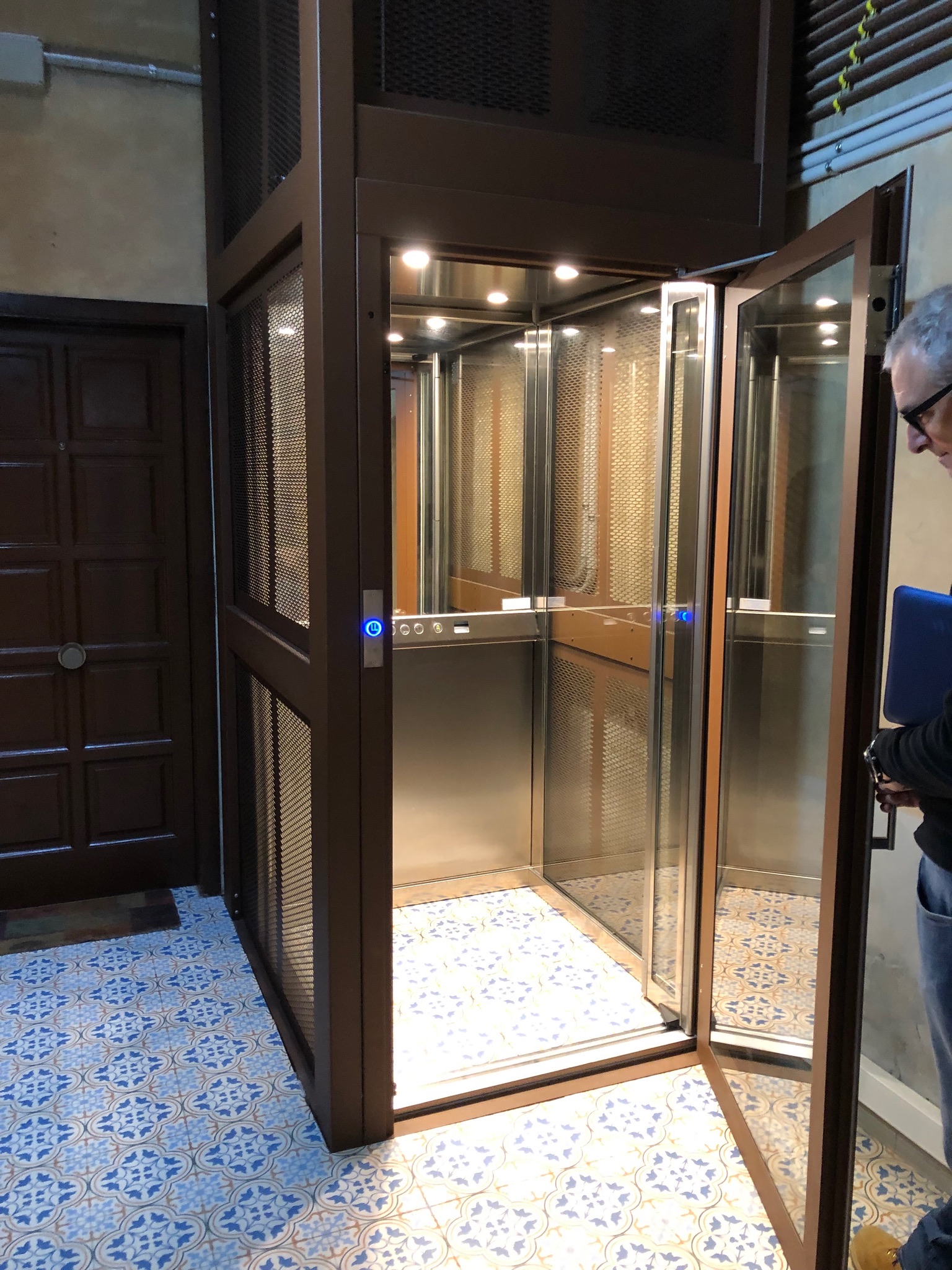
Project Home is a prepainted steel elevator shaft with a high degree of modularity, developed using 3D parametric systems that facilitate automated production. The structure is designed for installation of electrically or hydraulically operated systems, and is equipped with components that allow adjustments during installation. The infill panels, which can be glass or opaque, are installed from the inside, creating a smooth interior line that ensures user safety even in cases of cabins without walls or doors. Electrical connection cables can run through vertical and horizontal profiles.
The facility includes a variety of accessories and options, such as glass covers, canopies, ventilation systems and landing walkways. Anti-corrosive treatments and painting are carried out through industrial processes that ensure extreme durability and high aesthetic quality. All components and assembly systems are developed and tested on a large number of installations. The delivery includes a dedicated calculation report according to Eurocode 3 – UNI EN 1993-1-1:2005 and CE marking according to UNI EN 1090-2:2018.
Continuous development and a large number of installations over about 25 years guarantee technical, aesthetic and functional performance. The linear design and wide range of finishes allow the structure to easily fit the image and identity of any installation context.
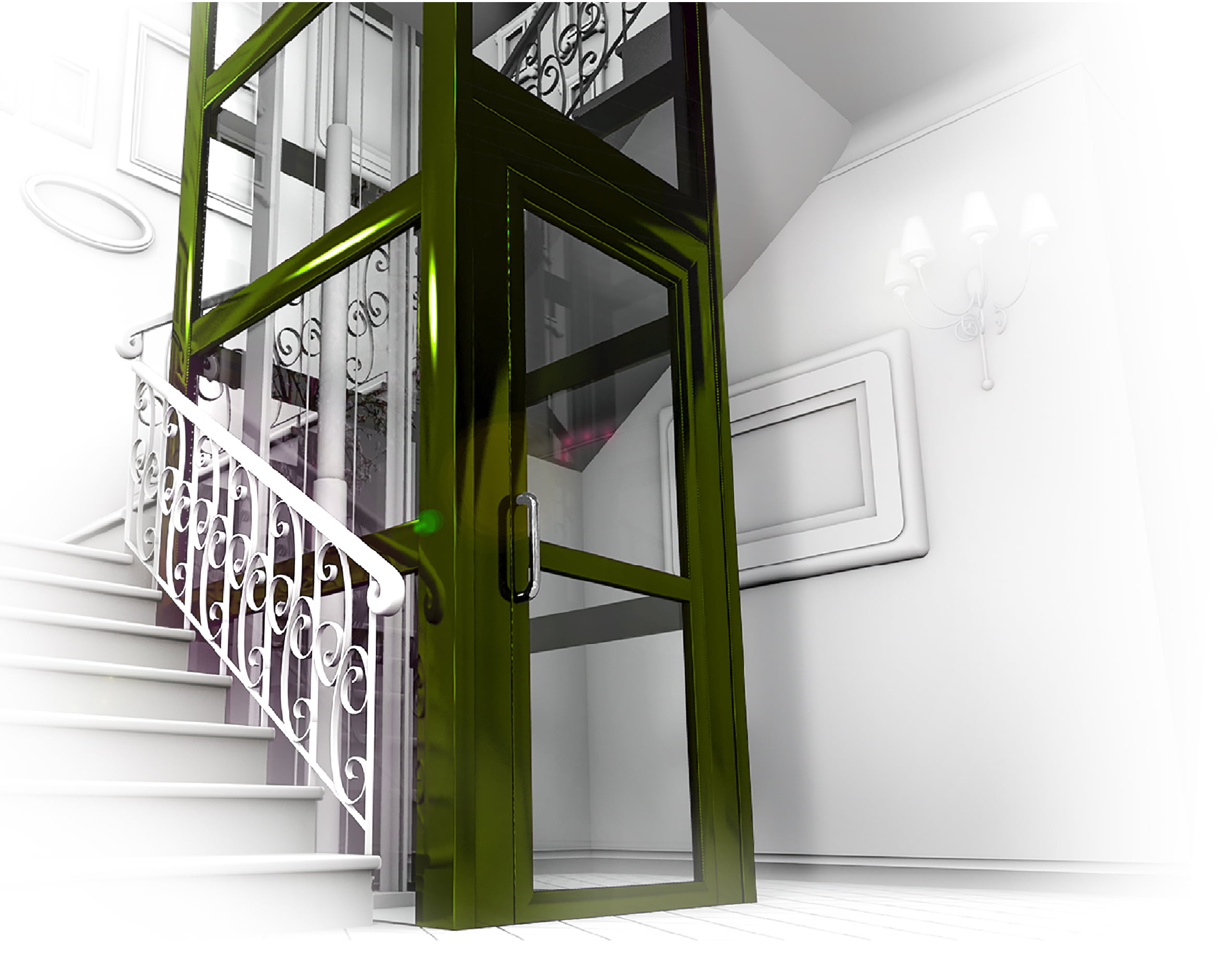
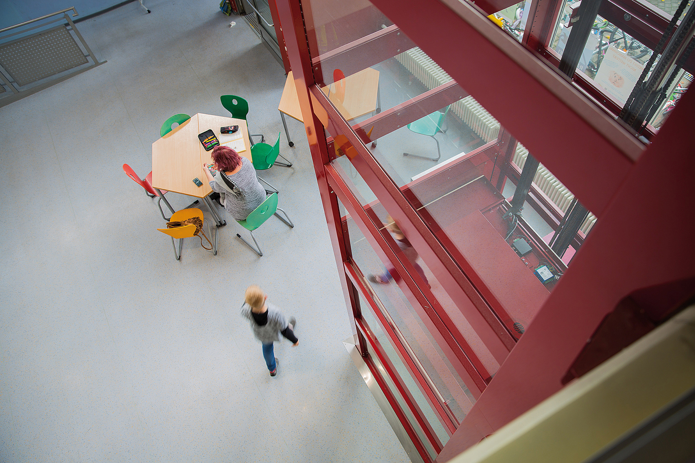
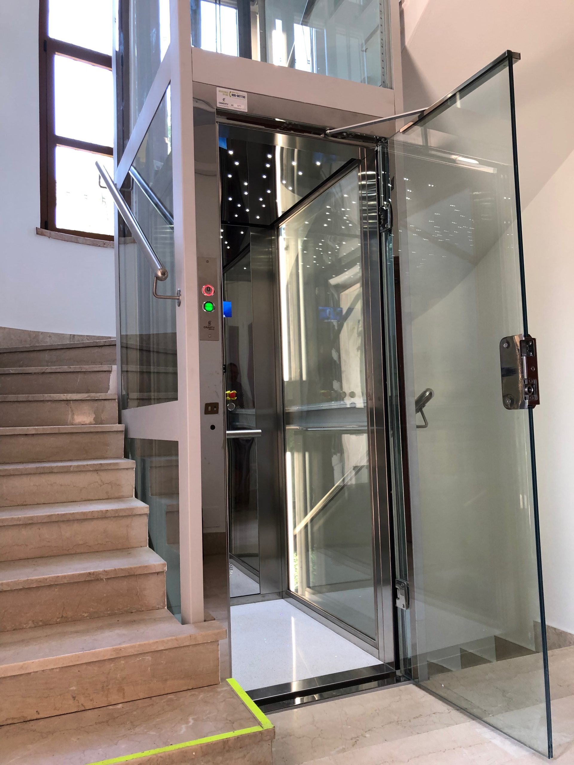
INSTALLATION INSIDE THE STAIRWELL
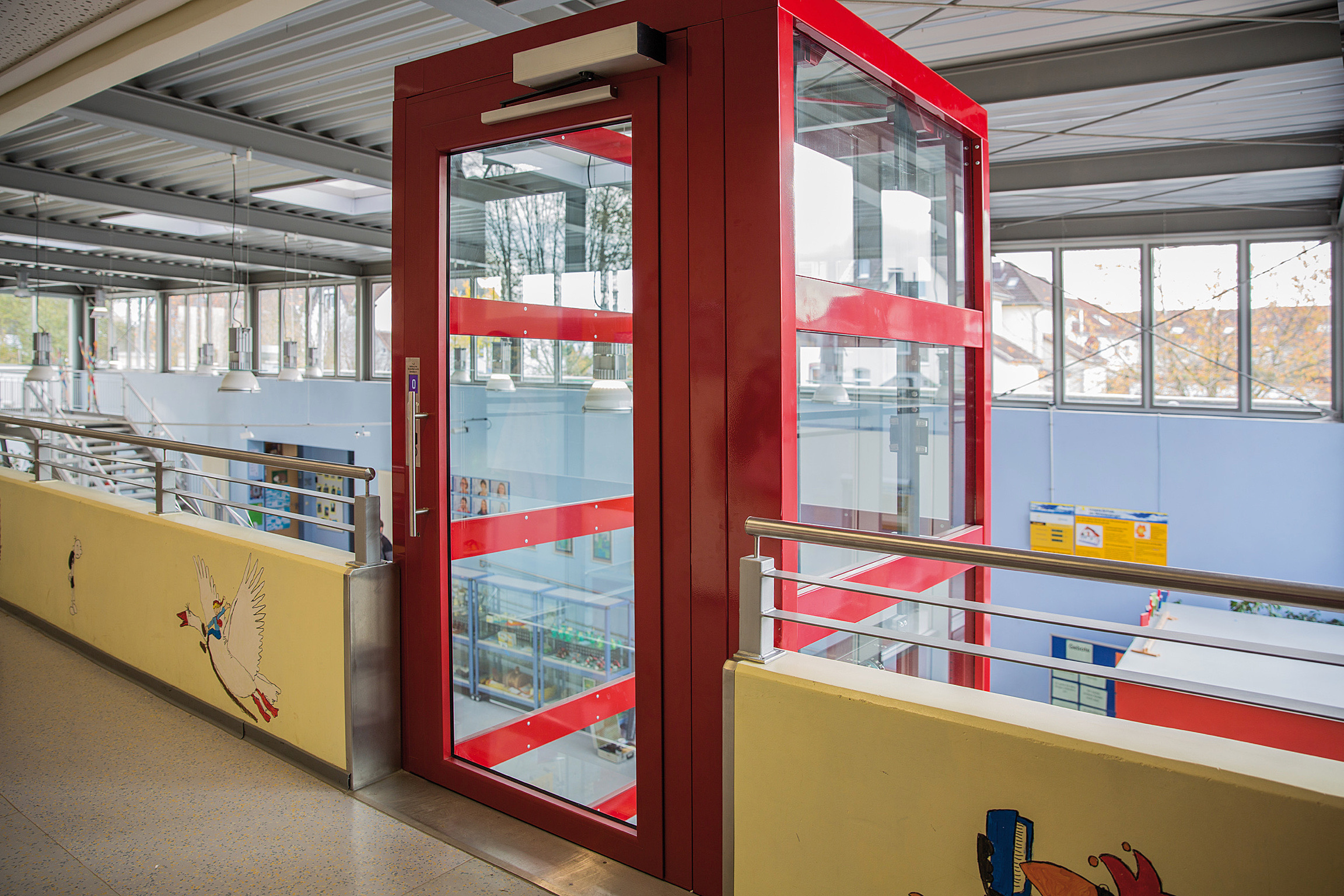
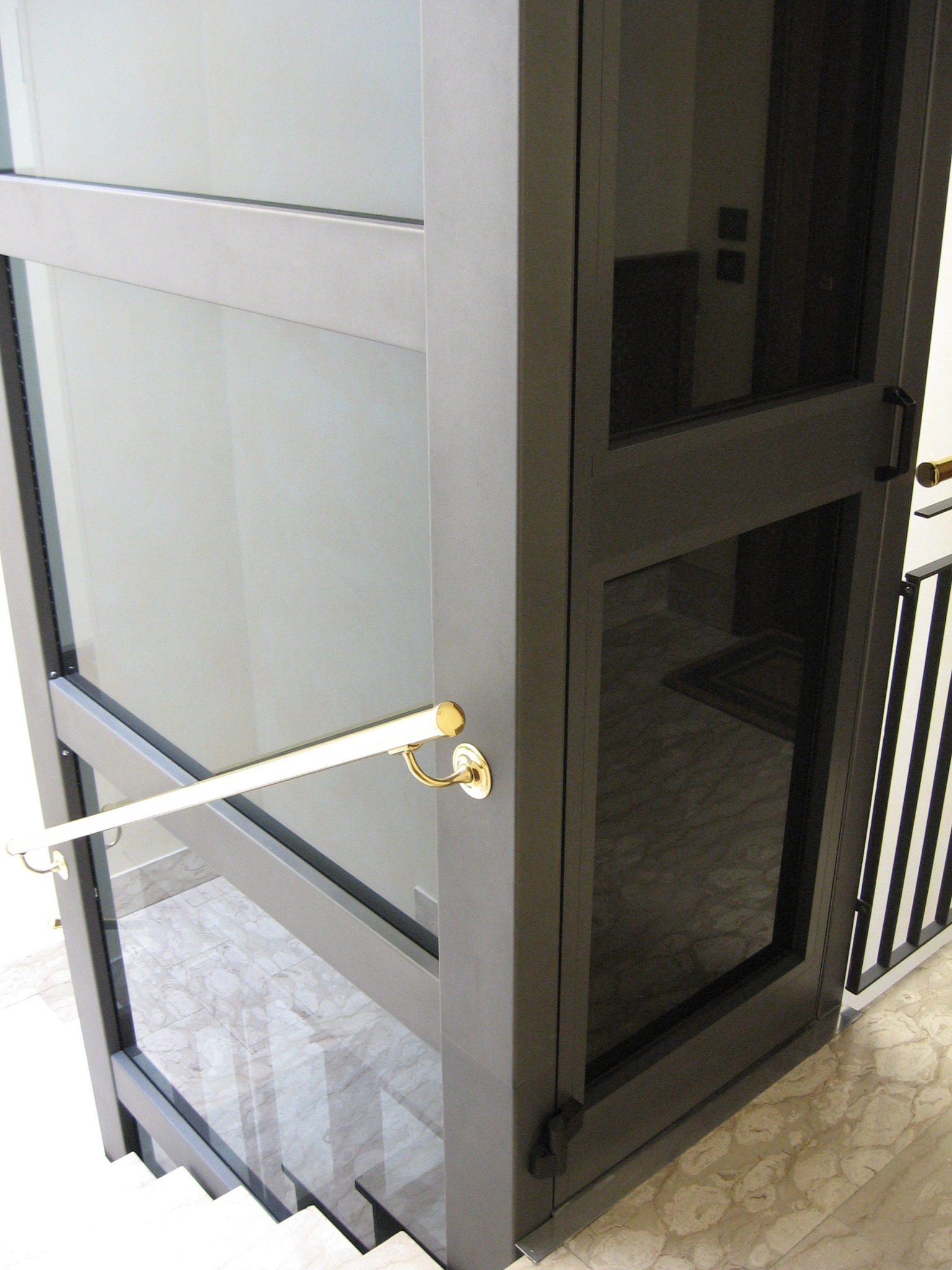
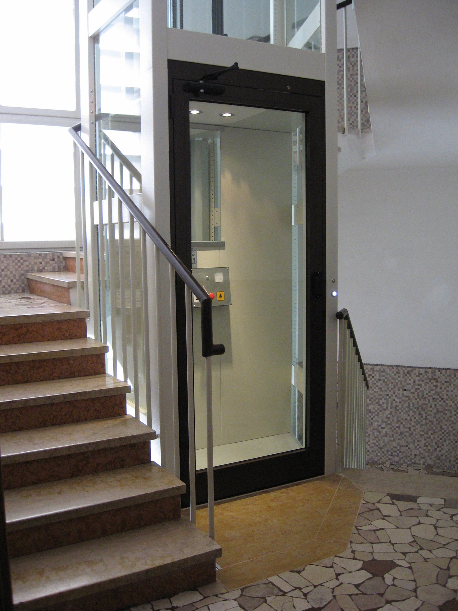
It is possible to place the lifting platform compartment inside the stairwell. The small thickness of the compartment ensures a high possibility of insertion. However, if the minimum required spaces are not available, the necessary area can be obtained by reducing the width of the stairs to the minimum allowed. In this case, the lift platform compartment can be used as protection by installing a handrail profile directly on it (available as an option).
This intervention ensures the construction of a regulation-compliant elevating platform, making it accessible and functional for people with mobility impairments.
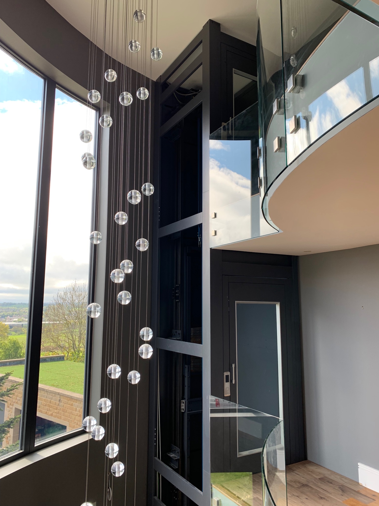
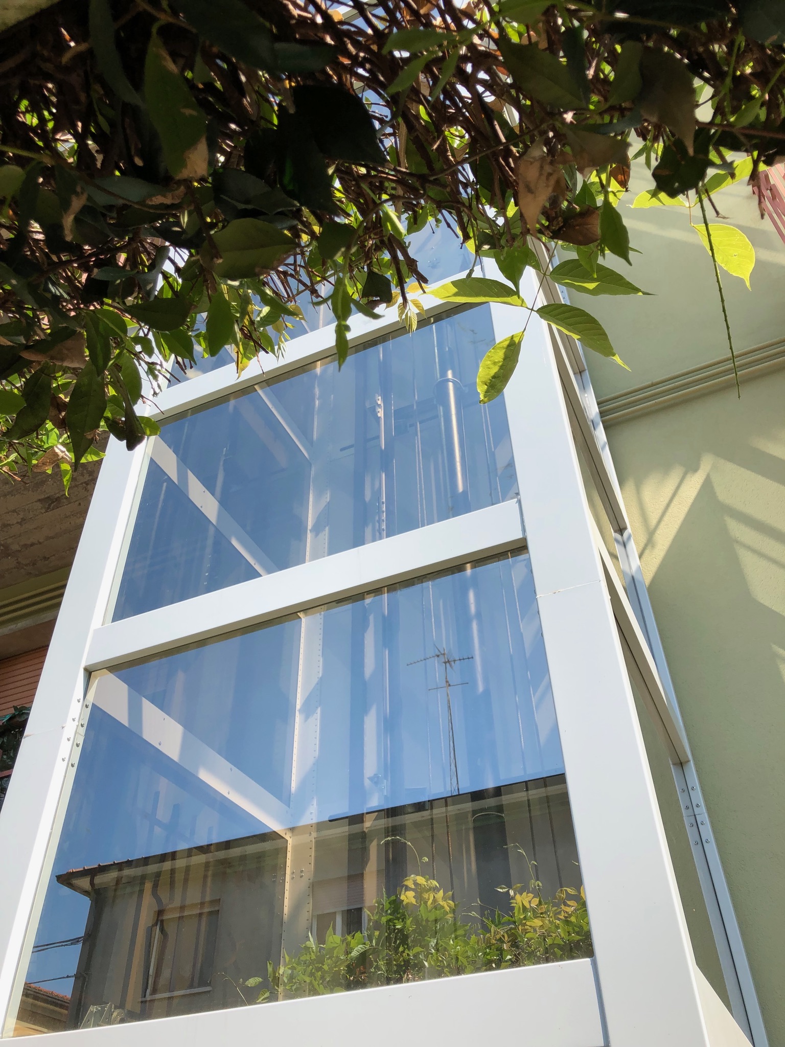
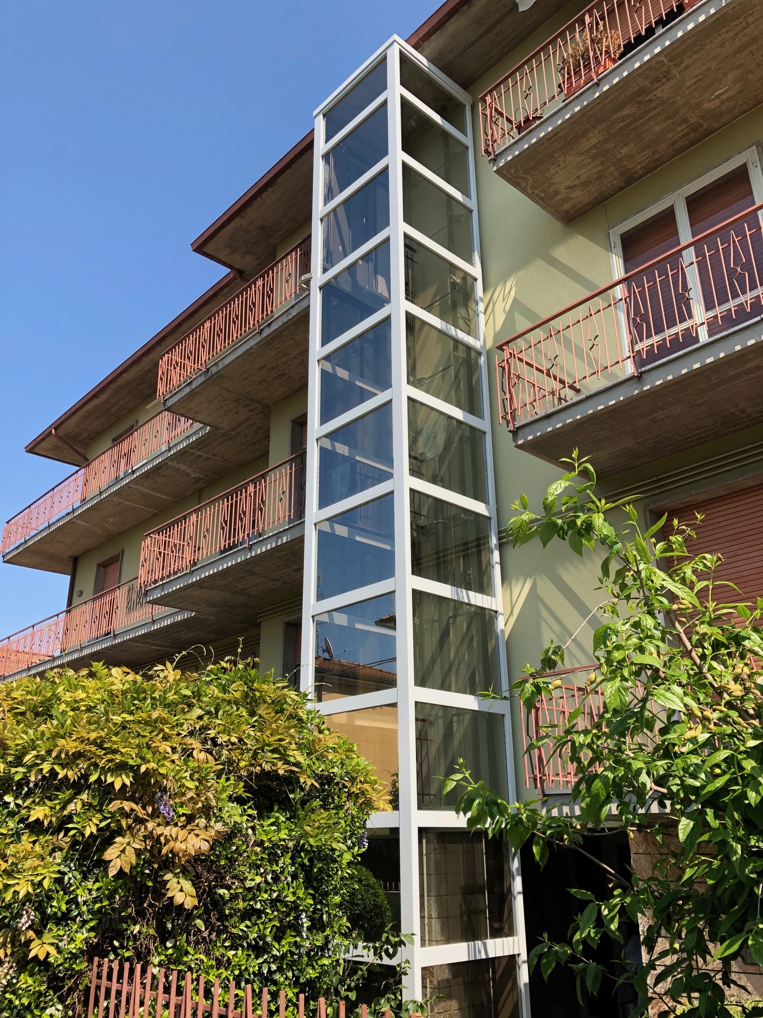
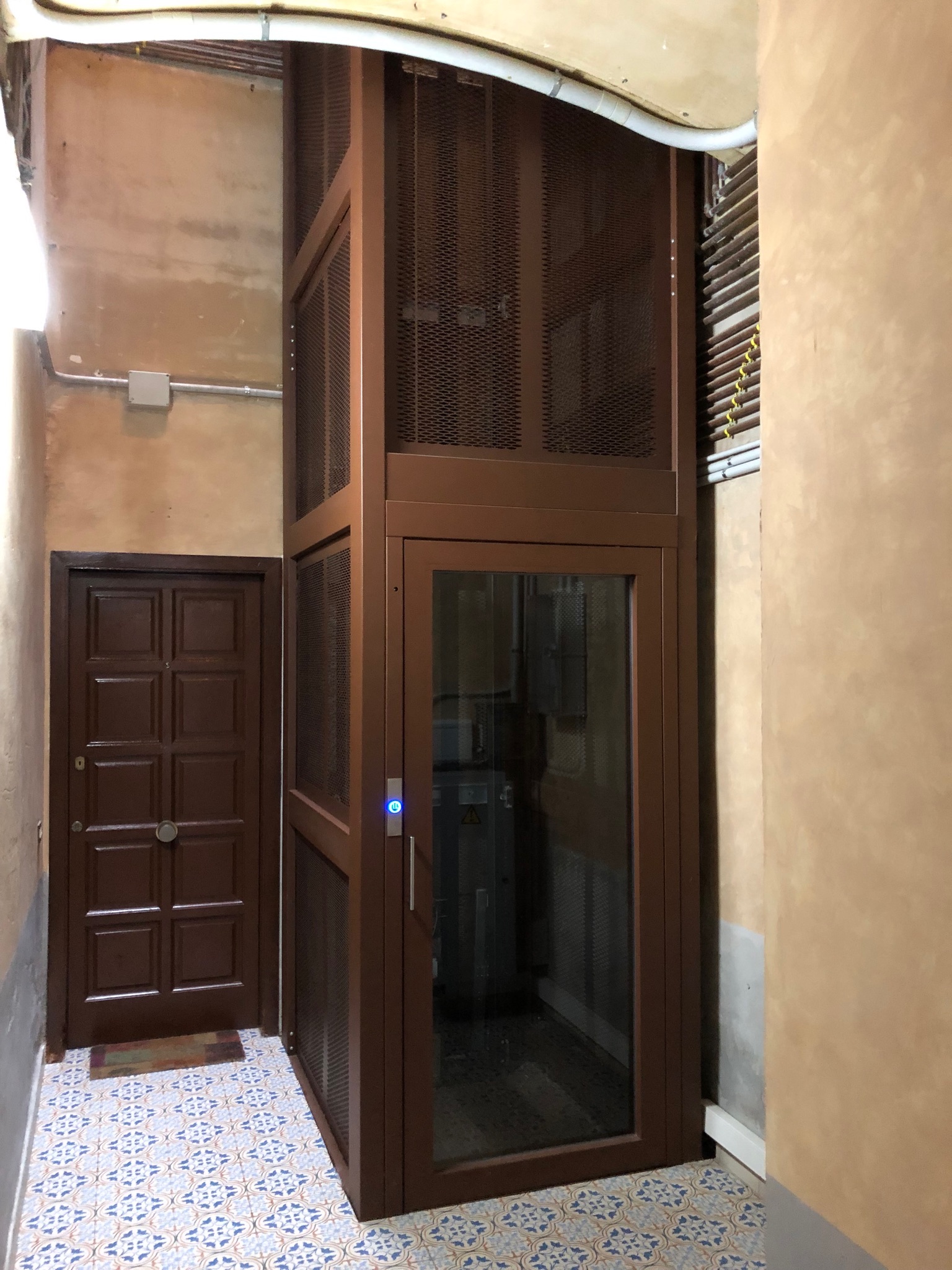
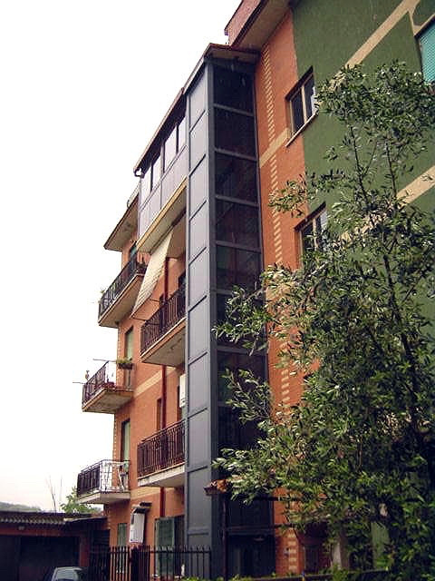
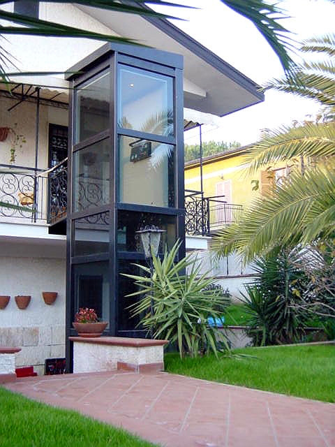
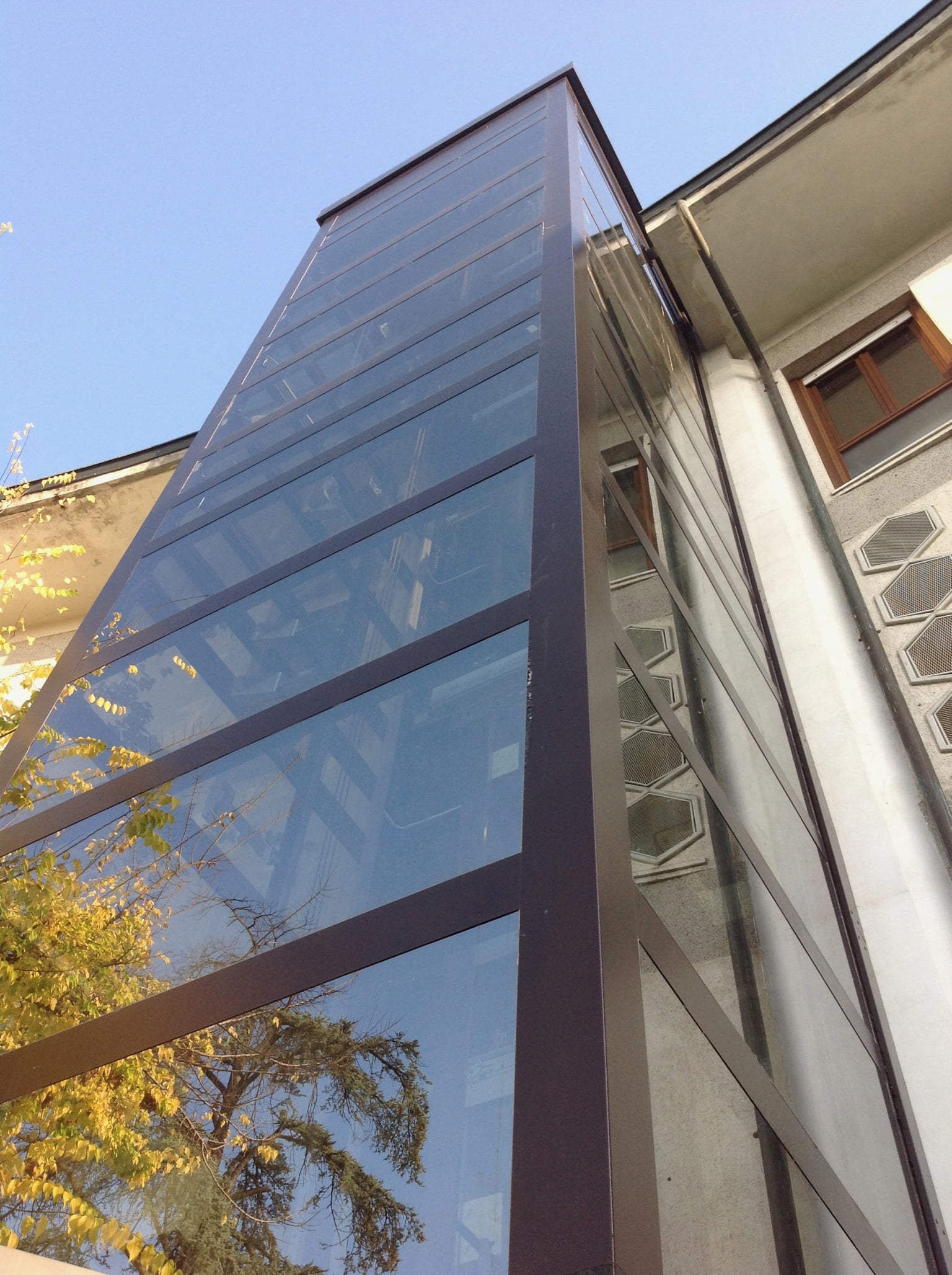
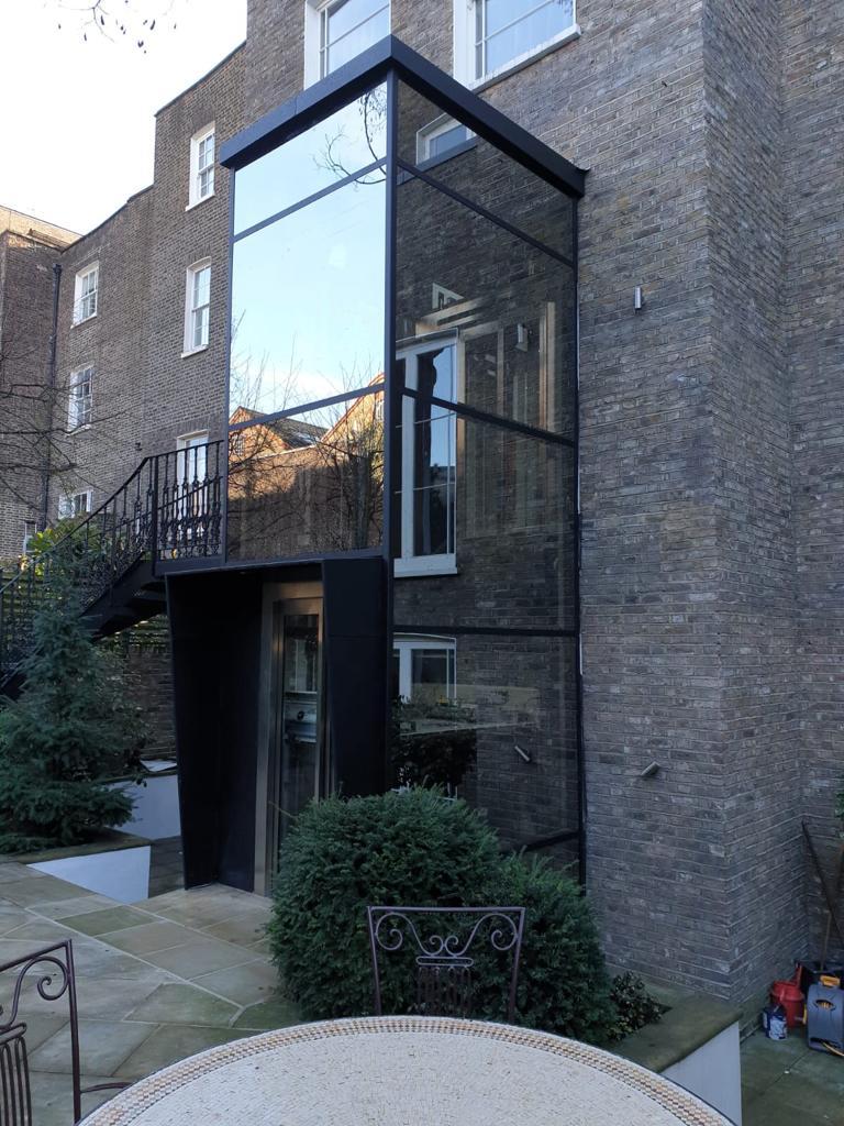
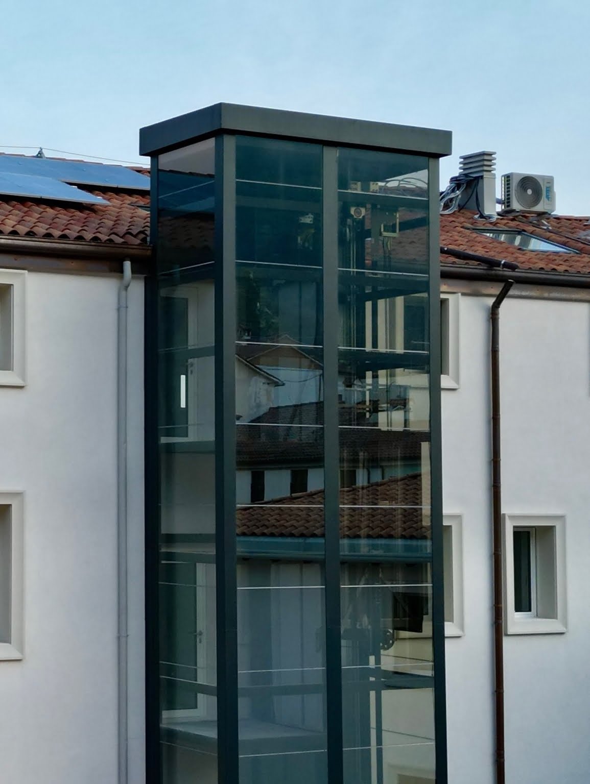
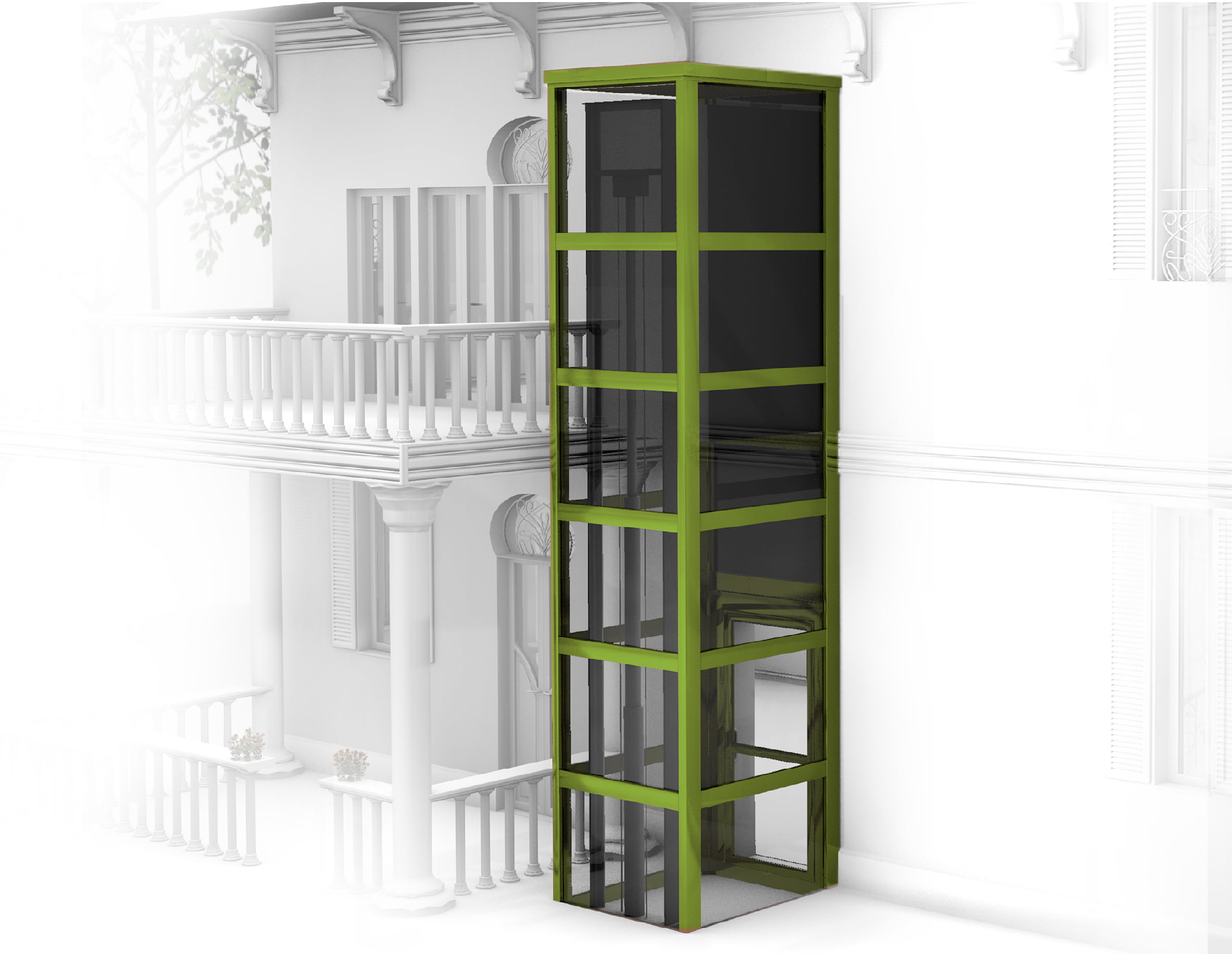
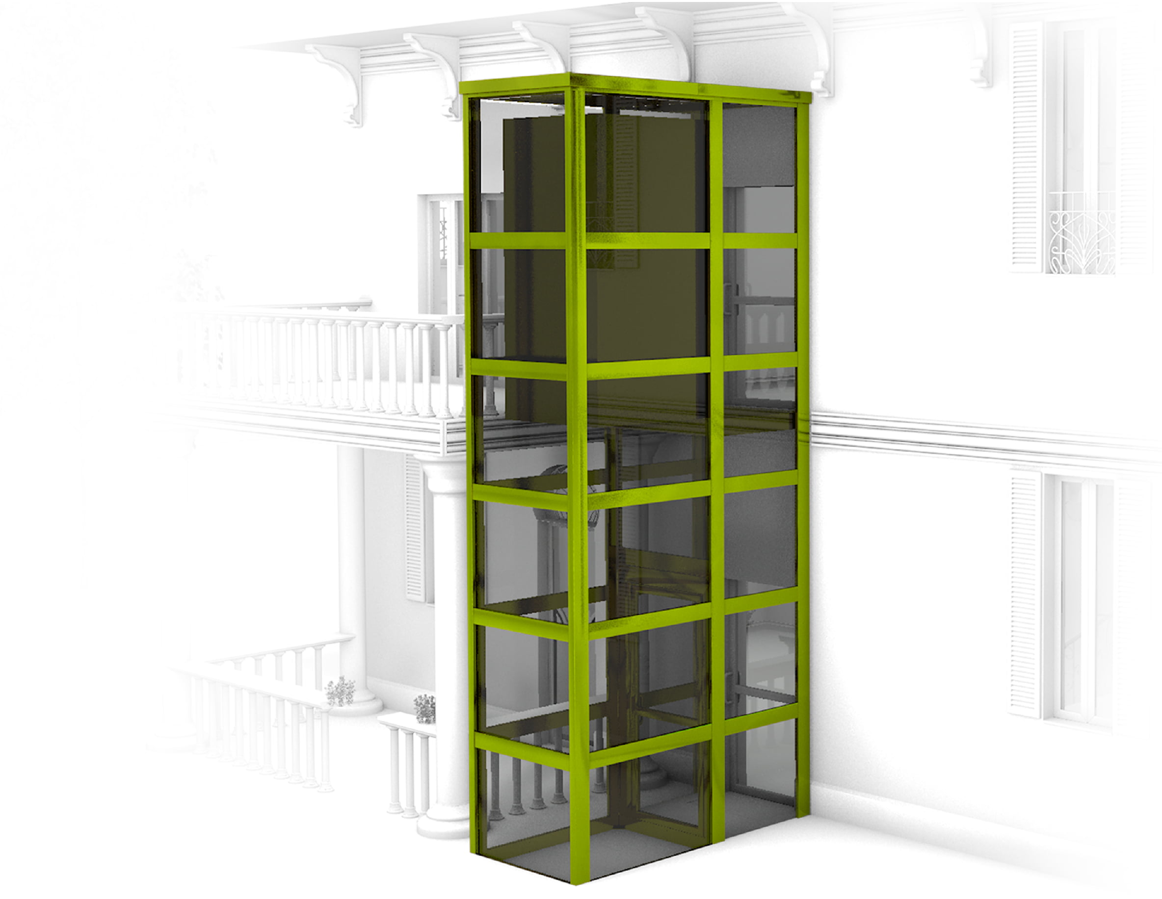
Installation close to a wall
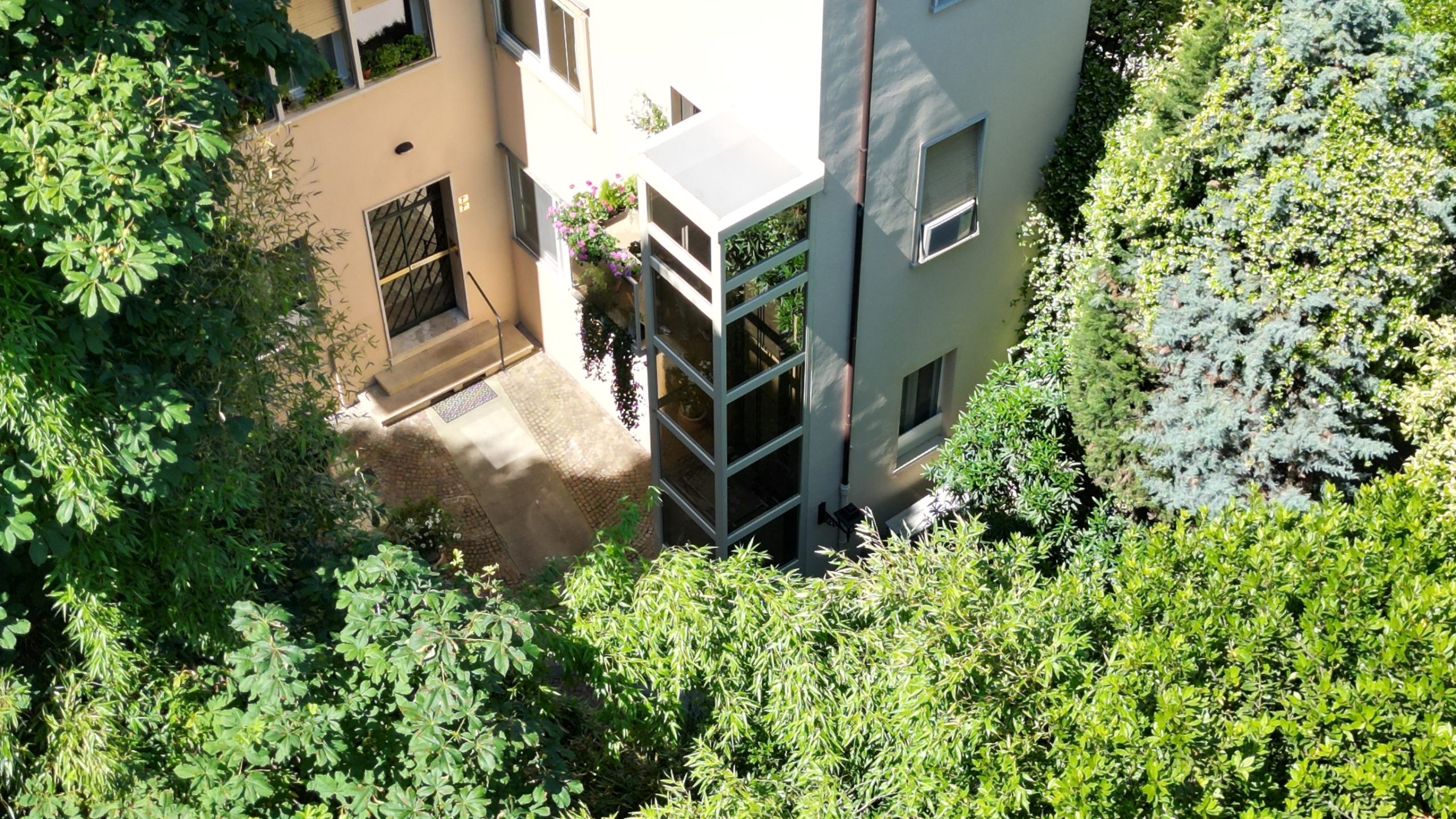
It is possible to place the lifting platform compartment close to a wall by arranging accesses through openings on the wall. It is also possible to add landings on opposite or side-by-side sides, allowing direct access to the outside or in other directions, adapting to the functional and architectural characteristics of the building.
This solution generally involves placing the plant and facilities outside the building, thus avoiding the occupation of interior spaces. It allows a high degree of adaptation to the layout characteristics of the building, making the elevating platforms highly usable even for people with mobility difficulties and ensuring easy and safe use.
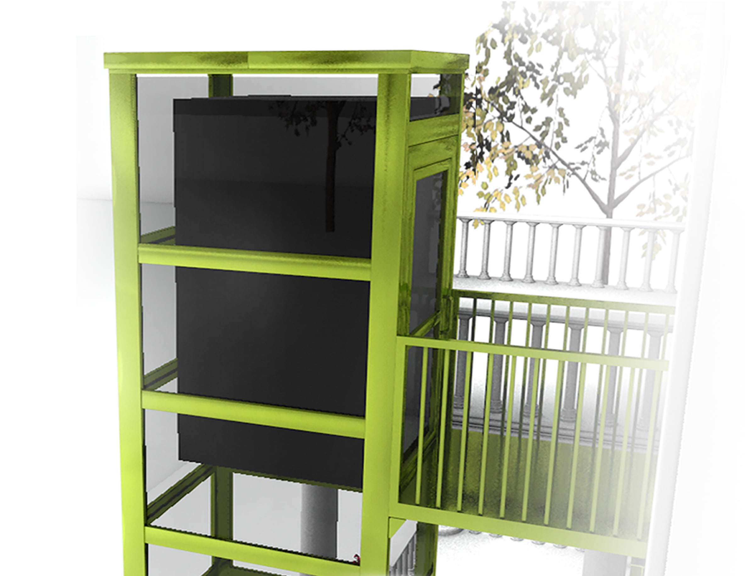
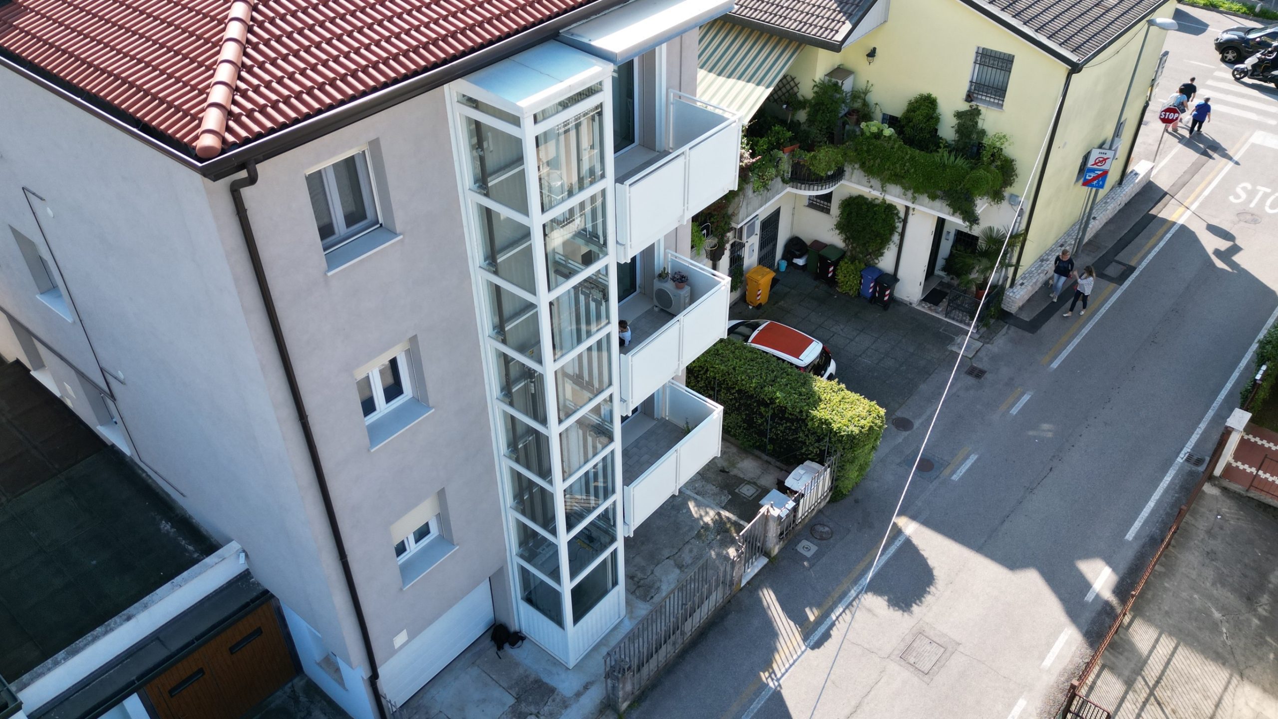
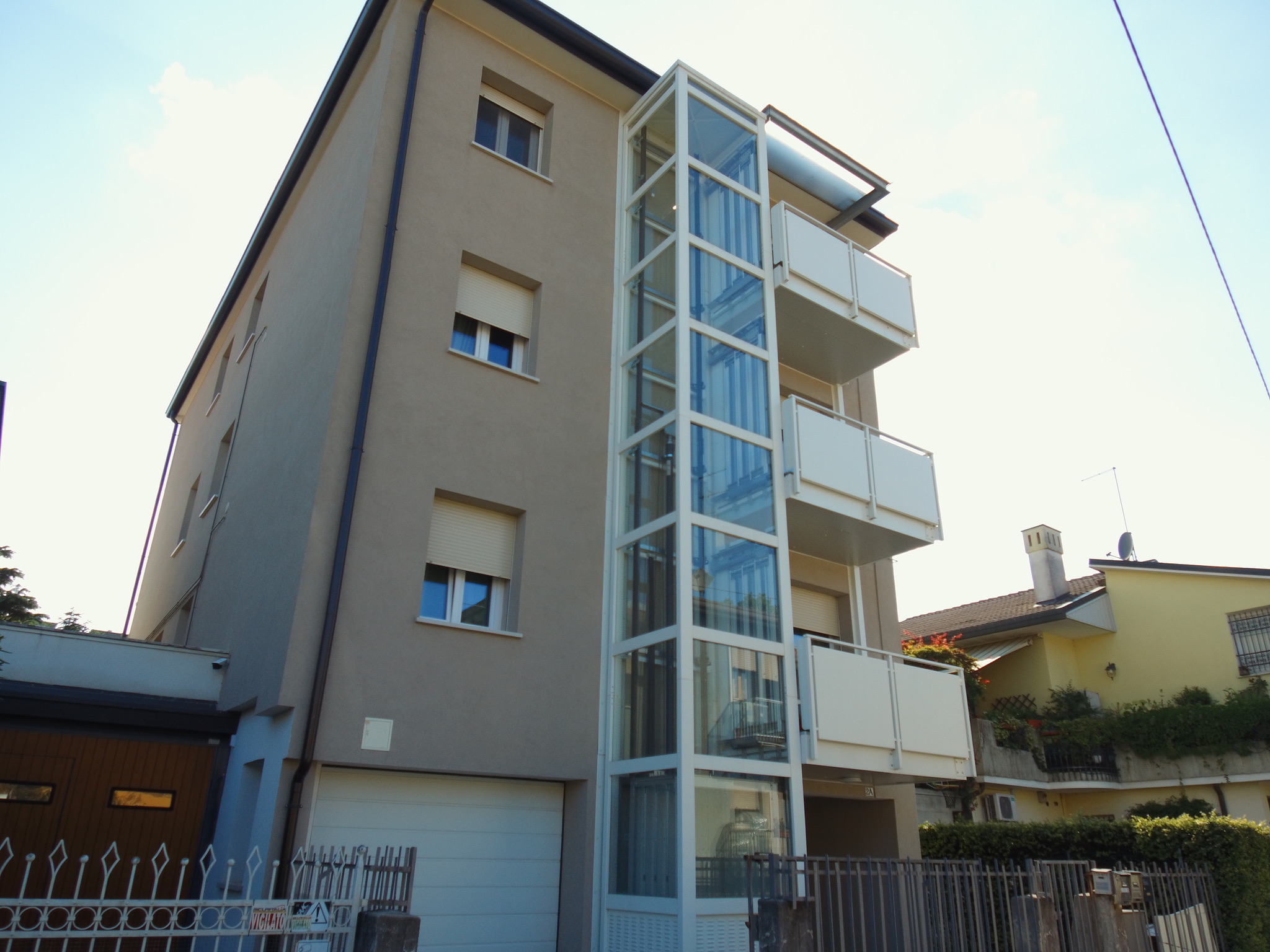
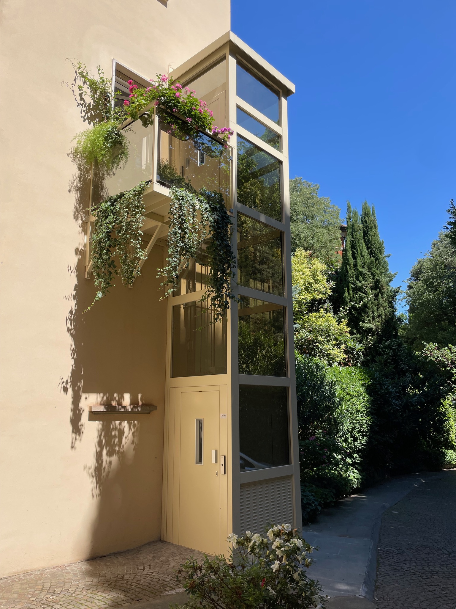
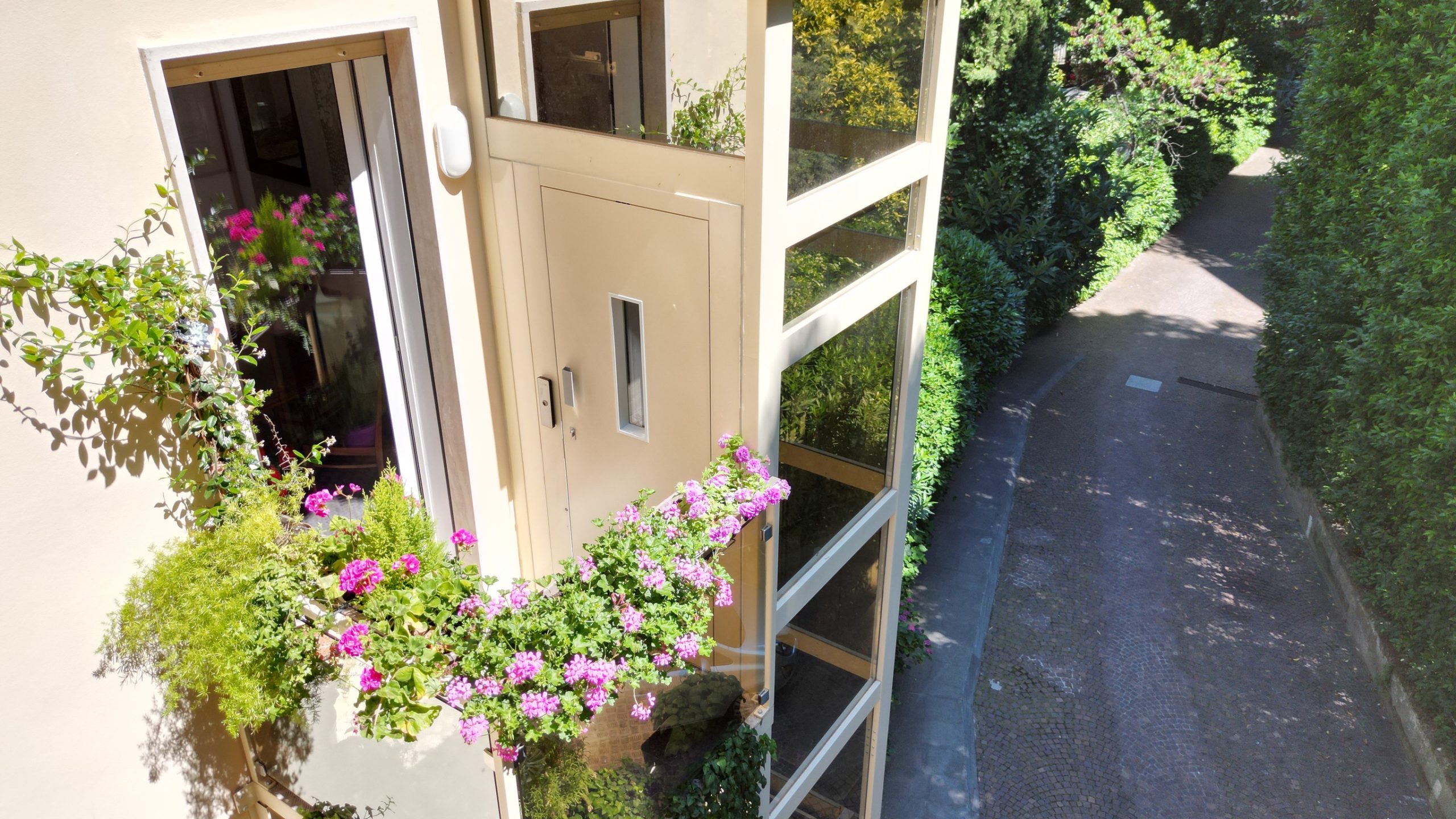
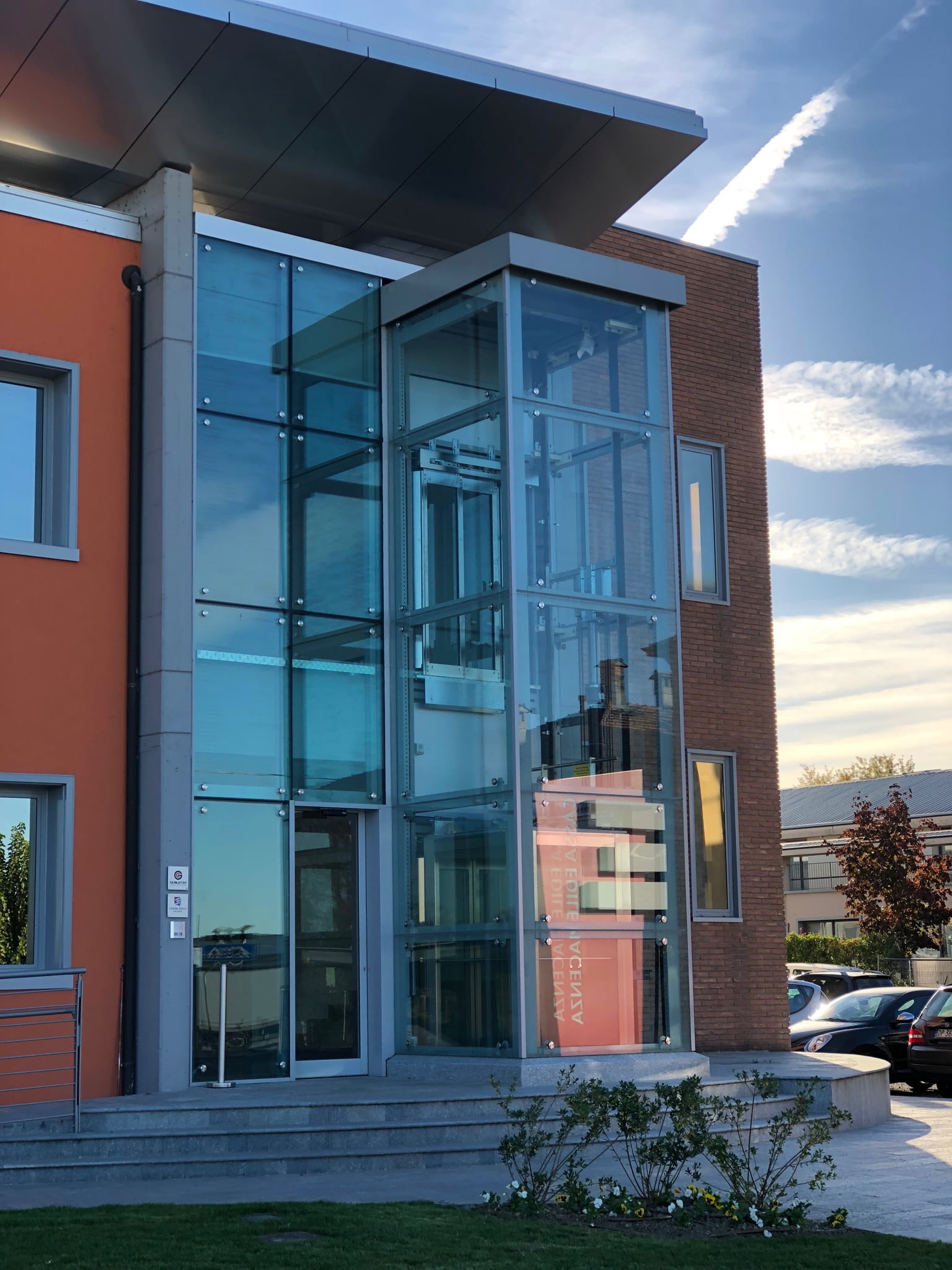
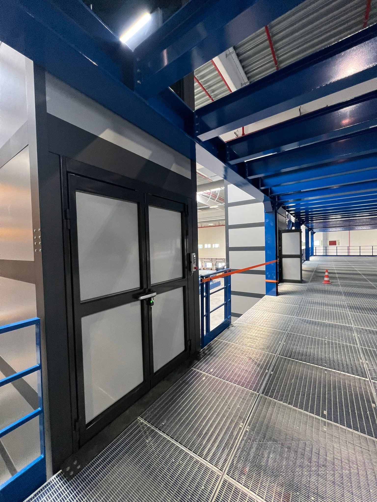
Installation with Open Landing Walkways
In buildings that do not have sufficiently large landing areas, elevating platform compartments with built-in balconies can be provided. This solution not only improves the usability of lift platforms, but also contributes to making buildings more inclusive and accessible, especially for people with mobility impairments, while ensuring easy and safe use for all. This option, adapted to current accessibility and safety regulations, also allows access to any tax benefits provided for the removal of architectural barriers.
Installation with integrated closed landing gangways
In buildings that do not have sufficiently large landing areas, elevating platform compartments with integrated enclosed landing walkways can be provided. These walkways improve usability and provide safe and comfortable access in all weather conditions. They can also be equipped with opening windows, thus allowing adequate natural light and ventilation to the connected rooms. This solution, which complies with current accessibility and safety regulations, improves the usability of elevators and helps make buildings more inclusive and accessible, especially for people with mobility impairments. In addition, it can allow access to tax benefits provided for the removal of architectural barriers.
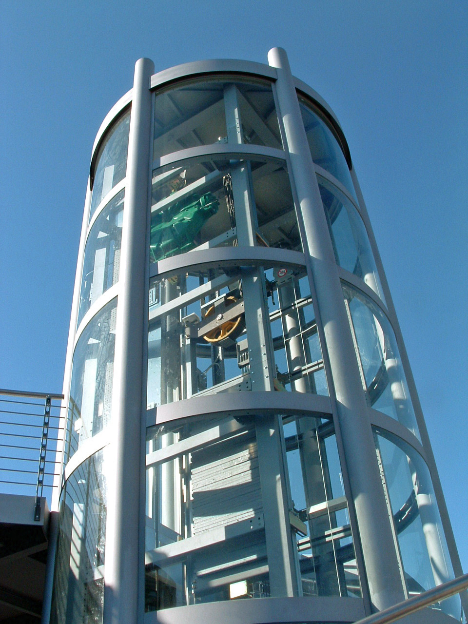
TECHNICAL DETAILS

The compartment for lifting platforms with capacities up to 500 kg is designed with assistance in a 3D environment, ensuring accuracy and adaptability. The structure, made of sheet steel, is processed by laser cutting, punching and CNC bending machines. Installation is by bolting and stabilization fasteners to the building, with a standard configuration involving connections at the base, landings, and header. Special configurations with free header are possible.
For outdoor versions, there is an antioxidant treatment performed by cataphoresis, while for indoor versions, the surface finish is done by powder coating. During installation, the compartment offers considerable adaptability, including the possibility of repositioning all horizontal profiles every 30 mm and fine adjustment of over- and under-door transoms. Rail support brackets are connected on profiles with continuous adjustment provision, allowing for adaptation and plumb during installation.

INTERACTIVE 3D MODEL

- 1
Heavy-duty beam with or without eyebolts. Repositionable during installation.
- 2
Horizontal profile for supporting heavy loads. Variable dimensions depending on loads.
- 3
Internal cable routing to horizontal and vertical profiles. Inspectable with removal of protective cover.
- 4Horizontal profile with continuous arrangement for fixing rail support brackets. Repositionable during installation.
- 5Vertical profiles with concealed joints. Complete with internal closing casing.
- 6
Base frame with integrated pit and plug-in joints. Installable by fixing with dowels.
- 7Roof for indoor or outdoor installation. Made in 2 parts, with drip-saving profile.
- 8
Stabilization frame with cross. Also made in 2 parts for easy shipping and installation.
- 9
Glass infill or sandwich panel. Installable from inside, also interchangeable during installation.
- 10
Generic horizontal profile. Repositionable during installation.
- 11
Horizontal profile with provision for fixing manual or automatic doors. Repositionable and adjustable during installation.
- 12Door side compensator profile. Made to measure.
FINISHES AND ACCESSORIES
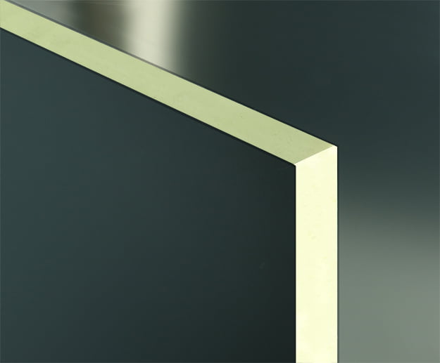
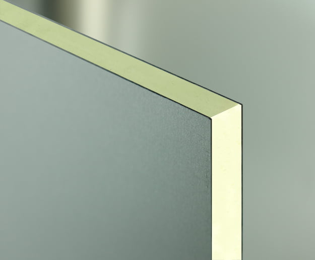
Glass and sandwich panels
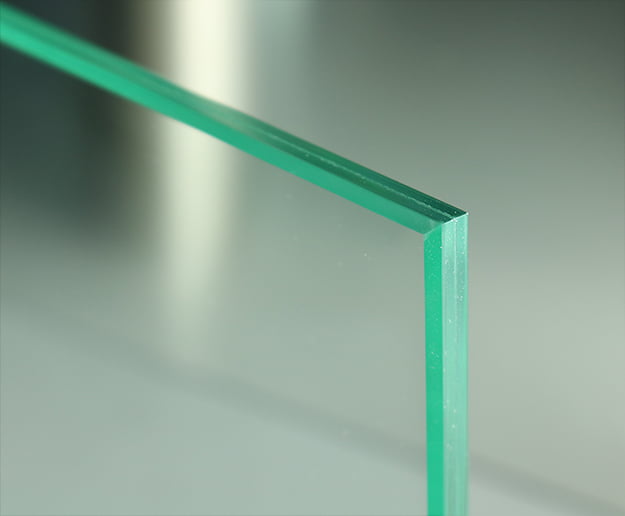
G1 – Clear
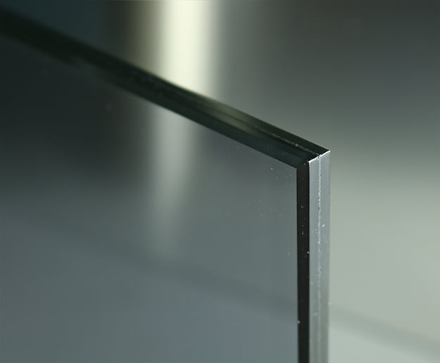
G2 – Smoked Gray
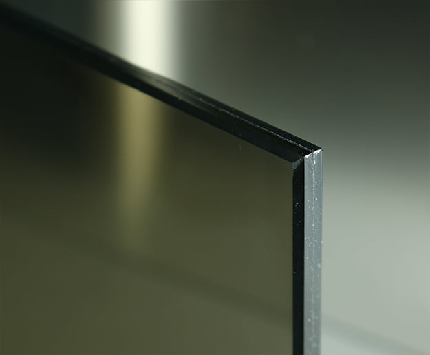
G3 – Smoked Bronze
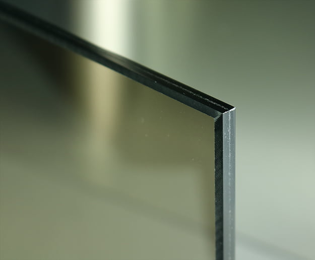
G4 – Stop Sol Clear
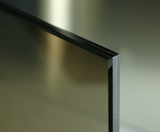
G5 – Stop Sol Bronze
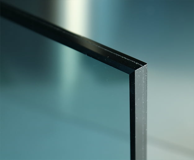
G6 – Stop Sol Dark Blue
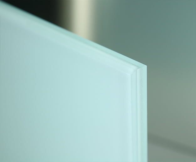
G7 – Opal
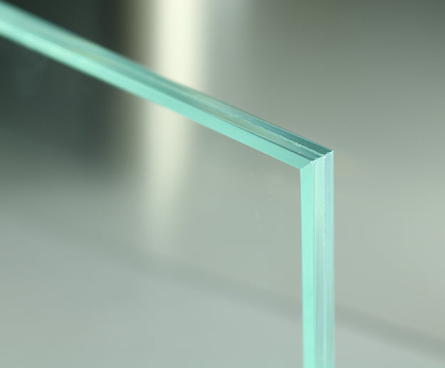
G8 – Extra Clear
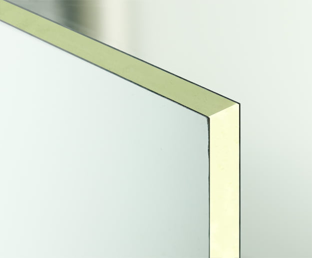
W1 - RAL 9010
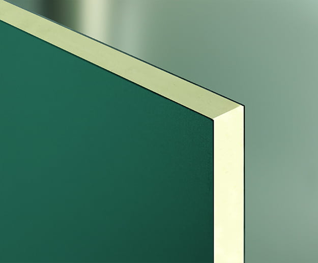
W2 - RAL 6005
W3 - RAL 7024
W4 - RAL 9006
G1 – Clear
G2 – Smoked Gray
G3 – Smoked Bronze
G4 – Stop Sol Clear
G5 – Stop Sol Bronze
G6 – Stop Sol Dark Blue
G7 – Opal
G8 – Extra Clear
W1 - RAL 9010
W2 - RAL 6005
W3 - RAL 7024
W4 - RAL 9006
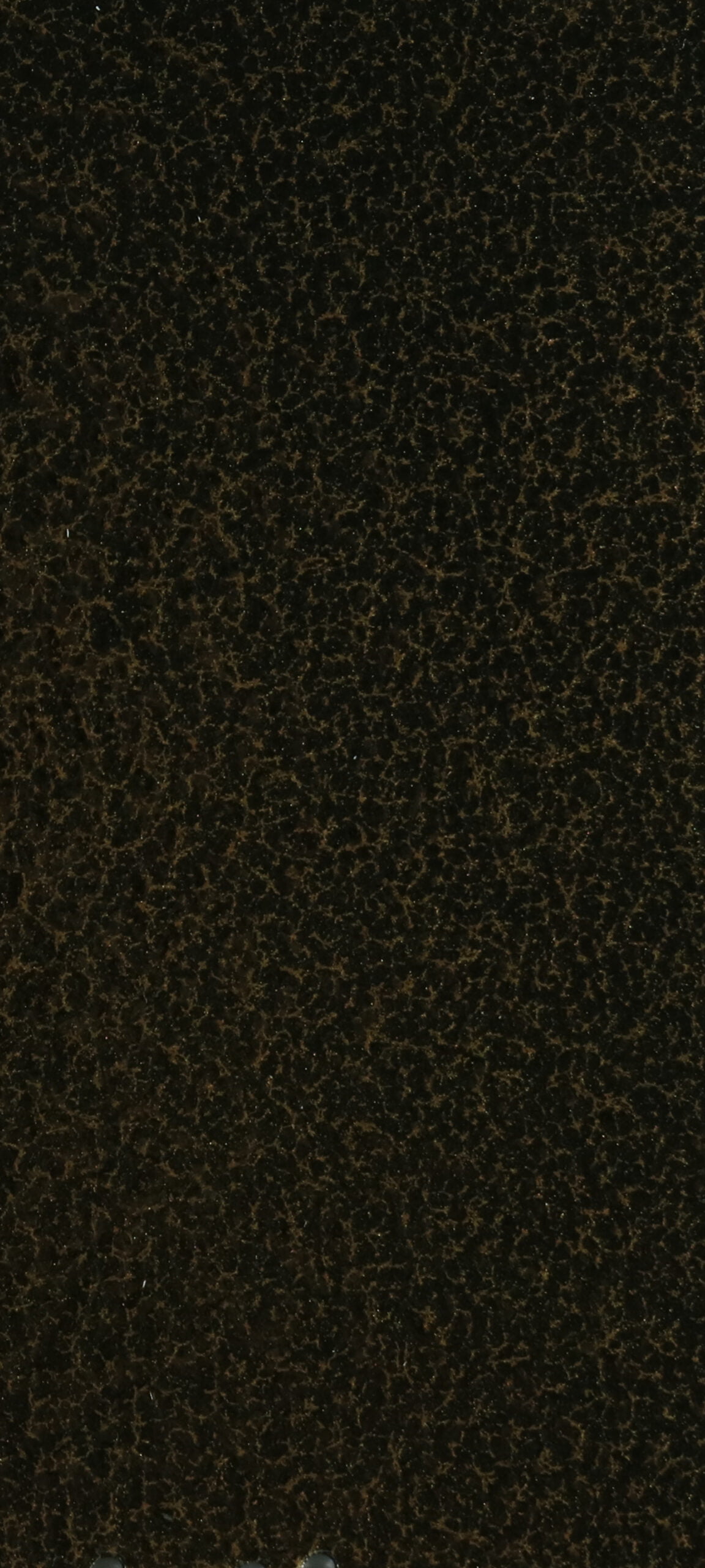
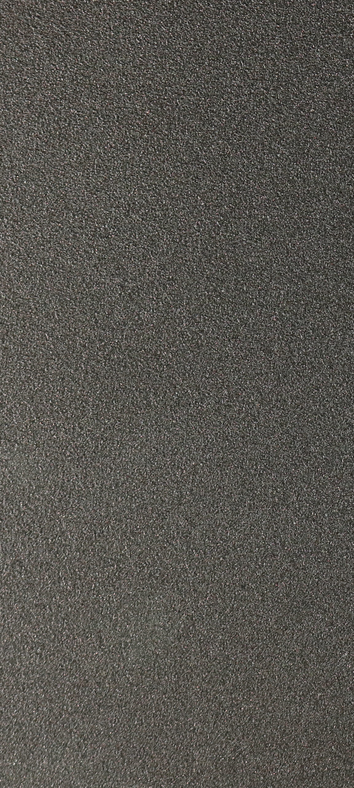
Paintings

C1

C2

C3

C4

C5

C6

C7
C8

C9
C10
C11
C12

C13
CS1

CS2

CS3

CS4

CS5

CS6

CS7
CS8

CS9

CS10
CS11
C1
C2
C3
C4
C5
C6
C7
C8
C9
C10
C11
C12
C13
CS1
CS2
CS3
CS4
CS5
CS6
CS7
CS8
CS9
CS10
CS11
Accessories
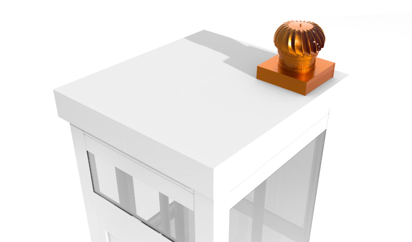
Wind vacuum cleaner
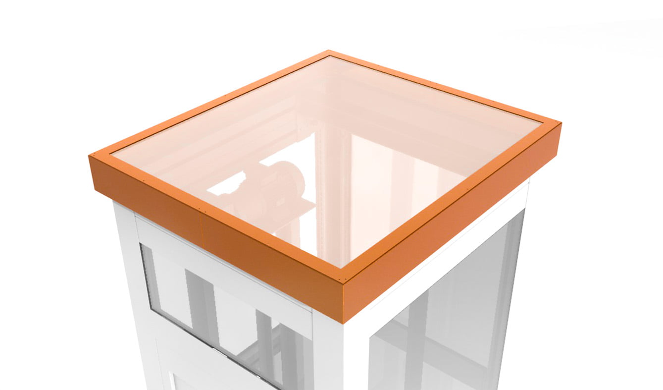
Indoor glass roof
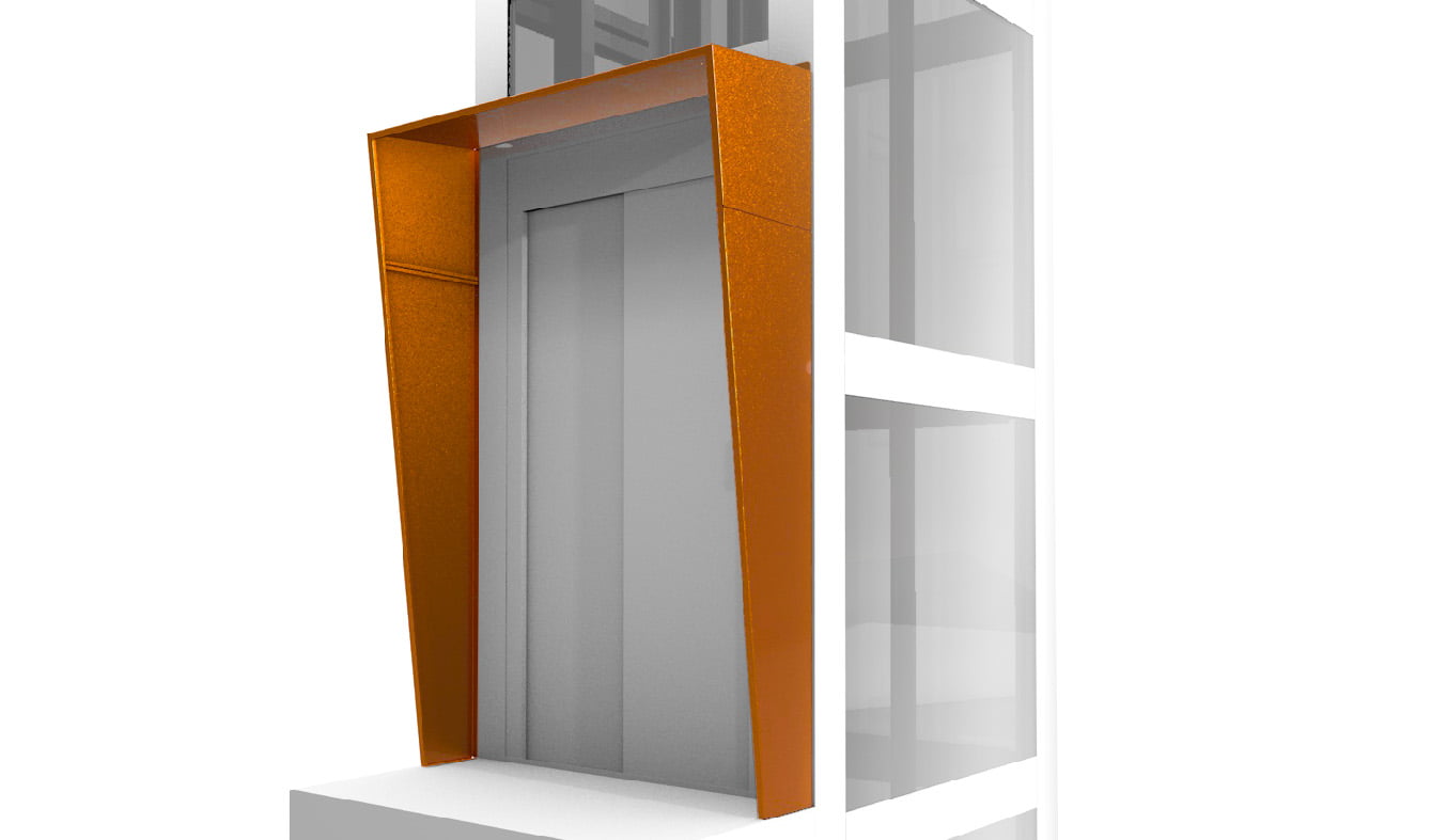
3-sided protection for door
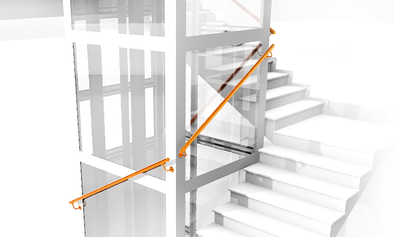
Handrail profile
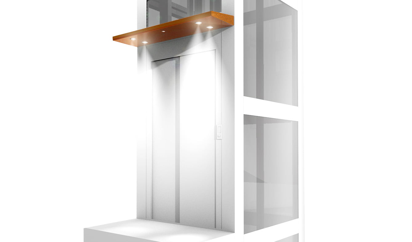
High brightness ceiling light
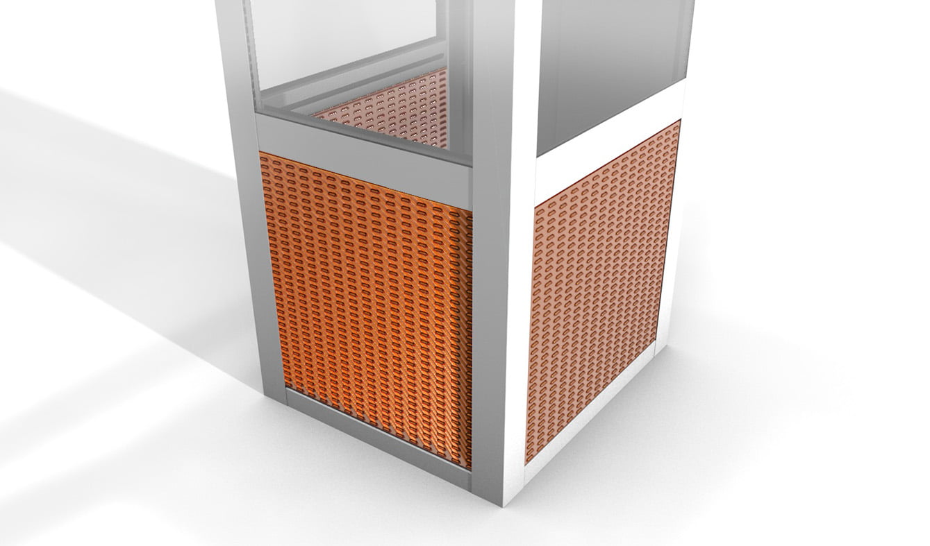
Sheet metal ventilation panels
Wind vacuum cleaner
Indoor glass roof
3-sided protection for door
Handrail profile
High brightness ceiling light
Sheet metal ventilation panels
SUPPLY DETAILS
The structure is supplied in a custom-made kit ready for installation on site by bolting and connecting to the host building. It is shipped in a sturdy wooden crate, suitable for shipping, and includes the following items:
- Frame components: All structural and connecting elements, complete with paint.
- Accessories: All required accessories, made to measure.
- Infill: Glazed or blind infill.
- Assembly kit: Galvanized steel screws and bolts, and accessories needed for complete assembly.
- Technical drawings: Detailed technical drawings.
- Manuals: Detailed documentation for installation and use.
- Calculation report: Dedicated calculation report in accordance with Eurocode 3 (UNI EN 1993-1-1:2005).
- CE Marking: Marking according to UNI EN 1090-2:2018.
The structure is available with or without buffering. Alternatively, the technical specifications and dimensions of the planned infills are provided. Excluded from supply are dowels or chemical anchor for connection to the building, and silicones.